Stirling
Engines
and Plans
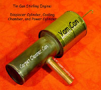
Tin can stirling engines,
walking beam stirling engines, hot air engines, stirling plans, hot air engine plans, Stirling
engine plans,
external combustion engine, Stirling plans, hot air engine plans,
Stirling
Walking Beam Engine, Sterling Engine (oops!)

Tin Can Stirling
Website
Hot
Air Stirling
Engine Web
Page
Email Me By Clicking Here
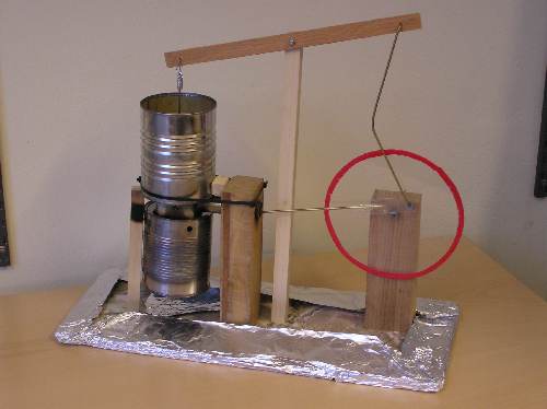
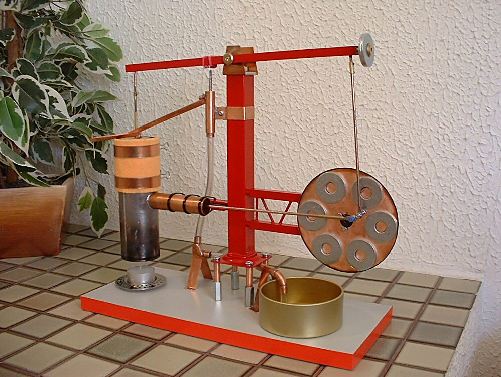
Tin Can
Stirling
Walking Beam Plans
Free!
It Really Works!!!!
Plans for building. no charge, no catch.
Really!
This site is here to help promote the
understanding of the primciples
of the Stirling engine.
It is not here to "profit" from that
information. So it is absulutly
free!
Plans, Online, Click Below
Tin Can Stirling Walking Beam
Engine Plans On Line
(New and improved images)
Plans in Word
format, click below
Tin
Can Stirling Walking Beam Engine Plans In DOC Format
158k file
Plans in PDF
format, click below"
Tin
Can Stirling Walking Beam Engine Plans In PDF Format
"How to time your engine if it is not
running correctly, click below"
Timing
your
engine
New!
Coypright Notice:
My plans are
copyrighted. If you are thinking of downloading my
copyrighted plans and selling
them on ebay (or anywhere) keep this in
mind,
I monitor ebay for such violations. I will persue the issue with
ebay and in the courts if nessesary.
I allow people to view them and use them to build a working unit
only. Not for your gain from my hard work.
Tin
Can Stirling Walking Beam
Engine Tips
and Hints
and
Changes
Includes: The new Power
Cylinder and Piston
The
Haigh piston & "Keep that displacer on!"
Oiling Tips
How to drill that brass bolt down the middle!
Stirling
Engine
Forum New!
Click Here
This forum is for all
kinds of Stirling and "Hot Air"engines,
not just the "Tin Can"engine
If you have a Stirling engine that you would like to show that
you have made from scratch (any kind),
or maybe have plans to share of it let me know. I will work with you to
make a webpage of your own.
Just email me! Email Me By Clicking Here
No copyrighted plans please (unless they are yours).
I respect the rights of others.
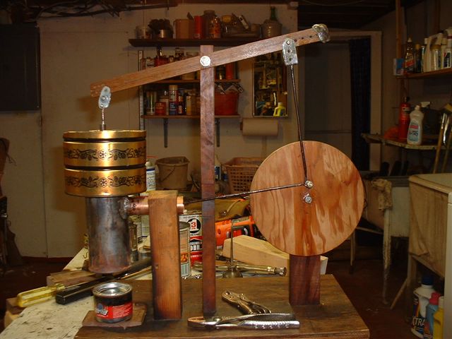
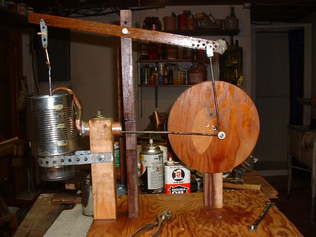
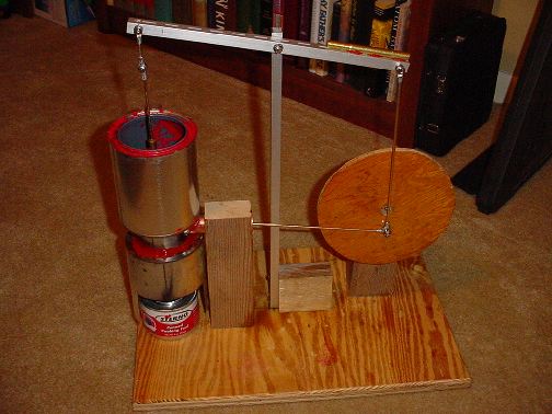
How
Does The Tin Can EngineWork?
This is an attempt to
explain
how this Stirling "Walking Beam" engine works.
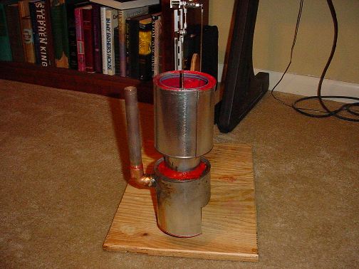
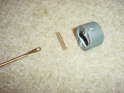
How the
tin can displacer works
If you understand the
"displacers" function, the rest is easy.
What is going on in there?? Here's your answer
Also answers "how much clearance is between the displacer piston and
the displacer cylinder and why"
Want the entire thing!!
Here Are Two different ways to explain how
the entire engine works.
How the
Tin Can Stirling "Walking Beam" engine works #1
Partially animated (you can stop it as
you
go)
or
How the
Tin Can Stirling "Walking Beam" engine works #2
The old version
A lot of people have made
this
engine.
If you have one, please email
me and I would love a photo to use on the page
Don't
miss out on the

At bottom of page
It includes photo's of working
"Tin Can Stirling"
Also videos of them running!!
New Designs
Or Different
New!
The Robertson Engine
by
Bernie Bowler
Horizontal Tin Can Engine
True horizontal tin can engine. Both
Displacer and power piston
It's taken a long time, but here it is!
Almost blew it
up!
Check it out
"How To
Build A Model
Air-Cooled
Hot-Air Engine"
Photos of
a Stirling engine built from the April 1961 Popular Science project
19 July 2005
Computerized Stirling
Engine!
Yes this engine is
assisted by a computer!
The new
"Computerized Stirling Walking Beam Engine"
News update: The "Computerized Stirling Engine"suffered catastrophic
failure on it's second run!
Gordon Harris
His Own Design
"The
Gordon Harris Stirling
Engine"
Gordon Harris
New "Two Cylinder" "Tin
Can Stirling" Engine!
" The Air Treatment Duplex Special "
Joseph Simone
A Take On The "Tin Can
Engine"
With a new type of drive called
a "Ross Yoke"
The
Ross Yoke Stirling Engine
You've got to see this drive
system work!
Brilliant!
Andi from Germany
Andi's
New Engine #2 (New Style) click here New!
Don't
miss out on the
At bottom of this page
It includes photo's of working
"Tin Can Stirling"
Also videos of them running!!
Have questions? Problems?
Email
me...Happy
to help out!!
They don't always work the first
time
out!! Most of the time they do!!
To email me click here
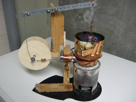
Cris LePage
Built August 2003
Martin Nobre
Built Aug 2003

Tony Gardner
Aug 03
(left photo) Tony used a "VCR Video Head as
a bearing for the flywheel/crank which is nice and smooth".
William Rushing
Dec 2003
Arthur Hillier
Arthur build three different engines.
One "full sized", one "half sized", and one
"one quarter sized"
Gunnar Aske
Built Nov 2003
Piston made of epoxy!
David Eaton
Somerset UK
Beam is about 6 inches long, power cylinder 1/2 inch bore.
Uses a sprit lamp!
Neil Brawley
Built May 2004
To see more of Neil's project
Click Here
Including a video of it running!
Neil Brawley's
Tin Can Engine Running!
(with sound!)
For IE users
If you're using Mozilla 1.6 or older download
and play off line or upgrade to Mozilla 1.7
Neil's
Stirling Walking Beam Engine Movie
301k WMV
file
Courtesy of Neil Brawley
Real Player Version
393k
RM file
AVI Player Version
1.8
meg AVI file
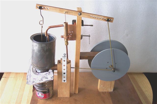
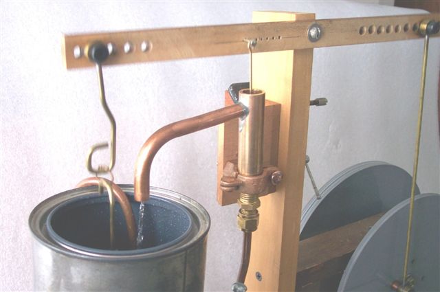
Water Pumper!!!
Gordon Harris
Built in June 2004
Gordon is an engineer in UK.
"The top half is half an aluminium filter casting with a tin can
JB welded to the bottom."
"In the UK we can get 28 mm O/D copper pipe and the piston was
the
plastic top of a
Pritt Stick ( it has three ridges that seem to work like piston
rings) which fitted perfectly and seems to
run best without lubrication."
"The engine runs very efficiently of a single night light candle,
and with two night lights does about 200 RPM."
"Because it was what they were originally used for, I fitted a
simple
piston pump.The piston and cylinder
from an old Mamod,and using bicycle ball bearings as inlet and
outlet
check valves in the fittings around
the cylinder. It pumps water fine again with only one night light
candle , but it runs faster with two."
Watch Gordon's run! (video)
Click Here
Gordon's
Stirling Walking Beam Engine Movie
1.2
meg AVI file
Check out Gordon's own design
The
Gordon Harris Stirling
Paul Wissgott
Built Summer of 2004
SE England
"-Added a balence weight to the walking beam (crank side), this
seems
to make the engine run smoother (no difference to speed).
-Added another rod to the crank area to reverse the engine rotation,
it turns clockwise as most engines turn this way.
-Heat proof super glue was used to seal transfer cylinder head,
and guide bush. (Thin Cyno 10 sec.)
-Walking beam & main crankshaft run in copper tube.Big end is
brass on mild steel pin"
"I did not do this but it may be worth experimention/ further
thought
If no lathe is avalible thick wall copper or brass tube may be the
solution to the
displacer guide bush tapped on the outside and secured with two
nuts seal with glue / solder"
"My engine will just about run on one 'nite-lite' candle but
turns
at a steady speed on two nite-lites,
solid fuel tablets or a very small butane flame."
Two Cylinger Tin Can
Engine!!
" The Air Treatment
Duplex Special "
by
Gordon Harris
Built in August 2004
Gordon is at it again!!
A two cylinder stirling tin can engine. It is driving a small
motor that is being used as a generator.
Watch his "new" video of this machine in action. Take note of the meter
the generator is hooked to!
Watch Gordon's 2nd engine running! (video)
Click Here
Gordon's
Stirling Walking Beam Engine Movie
1.8
meg AVI file
Ken Schmill
Built in January 2005
Has made two more since!
Terry Laffey
Built in January 2005
Has also made two more since!
Gordon McCall
Gordon is the first one to send me a
photo of his completed Stirling engine.
He has now completed a new engine with a water pump on it. It recycles
the tank water. He is now
adding a cooling system to that pump.
Click on the photos above for a larger view.
Check this out!
Stirling
Walking Beam Pump Plans
Newest Members of the "Hall
of Flames"
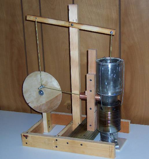
Donald D. Pointer
Up and running April 2005
Also Built by
Donald
D. Pointer
Slightly different approach to the tin can engine.
Horacio Licera
Argentina
May 2005
You can
contact Horacio by email at
With last modifications runs
at 120 rpm.
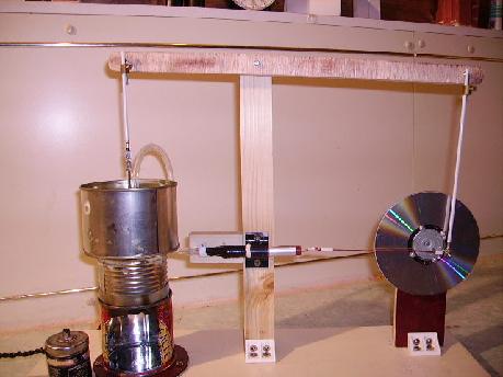
Joseph Simone
150 RPM on sterno and fresh ice
water
Joe's
Stirling Engine Movie
5 meg AVI File
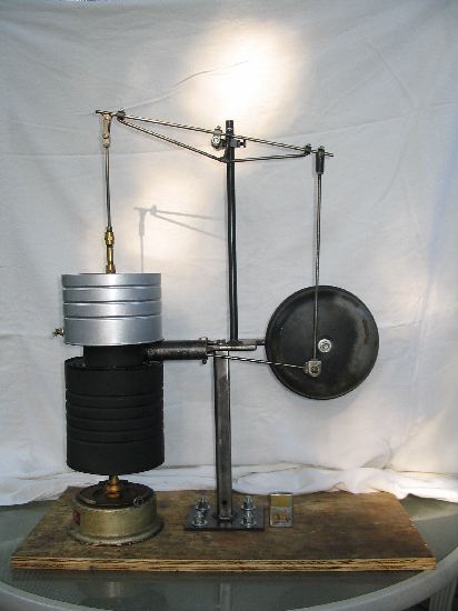
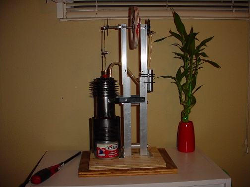
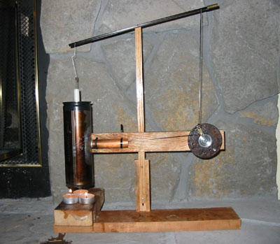
Darren Shabley
Completed July 2005
Ridgetown, Ontario, Canada
"It
is fairly large being 27" high and 21" long.(note the size of the Zippo
lighter at the base).
I am very pleased with my first attempt at a hot air engine. It runs
perfectly silent and up to approximately 180 RPM with heat coming from
a coal oil lamp.
Here are the particulars;
The displacer cylinder is made from a diesel engine oil filter.
The power cylinder and piston
were taken from an old shock absorber.
The flywheel/ crank is from a
farm tractor air cleaner
The main bearing is a valve
guide from a diesel engine with an oil hole
There are ball bearings inserted
into the connecting rod ends which I found at a hobby shop.
No machining was required, only
a welder, grinder, drill press, and a set of tap and dies.
The engine can be completely disassembled for future modifications if
required."
by Darren Shabley
|
Terry Koller
Made in 2003
Check Out Terrys Website at
terrykoller.com
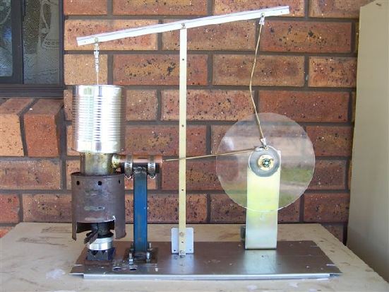
Rex James
(Swan
Hill, Victoria, Australia "Down Under")
Built 2005
"The
Air Wonder"
Main points.
Displacer
piston is made from Chinese Coconut Milk Tin. This is the only tin I
could find in the supermarket that didn't have a ring pull.
However,
being a liquid, I suspect it was easier to empty out than the tomato
paste version :)
Power
cylinder is 1" outside diameter copper (Aussie specs)
Power
piston is 1" aluminium rod turned on a lathe.
Connecting
rods are all bronze welding rod.
Connecting
eyelets are all "round electrical terminals" crimped then soldered to
the rods.
Main
bearing is from VCR head as per Tony Gardner's idea on your web page.
Simple and works a treat.
Specs.
Almost
runs on a single night light candle.
64
RPM on 2 night light candles
200
RPM on spirit heater. (Old kerosene lantern preheater)
Things I
may do in the future.
Heavier
Flywheel. I suspect the light plexiglass version I have is losing some
of it's flywheel effect.
I may
hook up a pump or generator etc as it looks great when these engines
are actually doing something.
...
and of course "Build another one" :)))
|
|
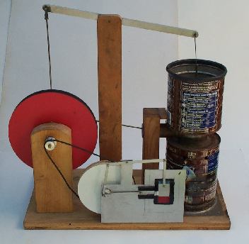
Roy Shepherd
Built 2005/2006
United Kingdom
Main points.
Displacer piston is made from a
cut down bear can; displacer cylinder a bean can; fire box an treacle
can and the water tank is a sponge pudding can.
Length 48 cm; Height 36 cm.
Power cylinder is 1 cm aluminium
pipe from B&Q
Power piston is made of
Polyester Laminatins Resin.
Connecting rods are coat hanger
wire, apart from the piston rod which is copper wire.
Connecting eyelets are all male
electrical terminals crimped then soldered to the rods.
Main bearing and fly wheel is
from a floppy disk drive with a CD riveted on to it.
Specs.
Turns at 110 RPM on a homes made
spirit heater.
How to make the Power Piston.
I got a length of the 1 cm
aluminium pipe and blocked one end with a peace of wood with a tiny
hole in the centre and threaded a length of copper wire through it and
out the top of the pipe � this is used to connect the piston to the
piston rod.
Next mix the hardener with the
resin and pore it into the pipe. When the resin as gone head, ease the
piston out of the pipe and clean up the edges with glass paper. Slide
the piston through the cylinder a few times and then it will be ready
for assembly.
You can get the Polyester
Laminatins Resin and hardener from car assessory shops
Roy Shepherd UK
|
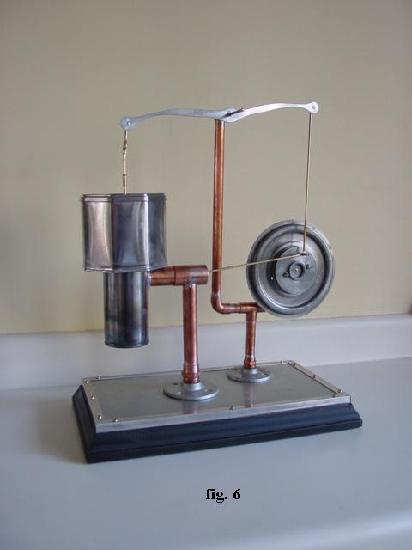
Joseph "Bill" Jackson
Built January 2006
|
I love to solder (as you can
see)and I built the basic framework out of rigid copper pipe.
Initially I had considered constructing the entire unit on a single
stalk and foot plate - but opted for the easier 2 piece construction -
one section to hold the main engine assembly and the other to hold
the fly wheel and the beam pivot. This allows for
minor adjustments in alignment.
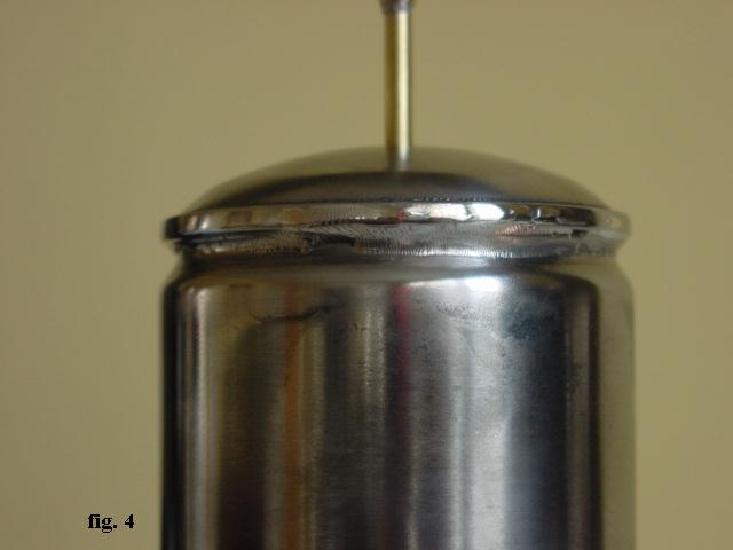
Some aerosol cans have recessed rims ( figs.1) - the bottom
from a second can makes an ideal top for the displacer cylinder and was
easily removed with an electric can opener. I soldered a brass tube
with 1/8"ID through this top to accept the 1/8" displacer rod ( fig 2 & fig 3). After a little
careful grinding of the cylinder's upper rim, this top fit
beautifully and the recessed area provided a great mating surface for a
tight solder joint ( fig. 4).
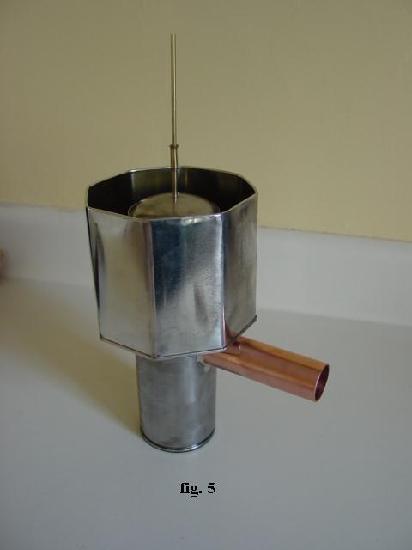
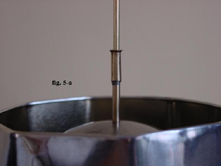
Fig. 5 shows the
completed assembly and water jacket - notice that a slightly larger
piece of brass tubing was soldered on top of the bearing tubing and
flared to accept oil during operation of the engine ( fig. 5-a).
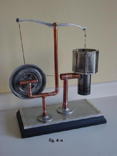
Figs. 6 and fig. 6-a show the front
and back of the completed engine respectively. The walking beam was cut
from 1/16" aluminum stock and the piston is epoxy (JB Weld). Although I
tried numerous other pistons , this seemed to work best. The
flywheel is a marriage of a motor flange salvaged from a defunct
vacuum cleaner and the flywheel / bronze bearing combination from
an ancient VCR (my wife has always wondered why I kept these items -
and many others - over the years - now I know - to build a
Stirling engine!) I use an alcohol chafing dish burner as a heat
source and get around 150 RPM.
My early prototypes using wooden supports and
plywood flywheel did not function well - so, my hat is off to
those who were able to get such an engine up and running. |
Additional Photos
Fig 1
Fig 2
Fig 3
Fig 4
Fig 5
Fig 5a
Fig 6
Fig 6a
Doug Simpson
Photo 1
Photo 2 Photo 3 Photo 4 Photo 5
Doug
Simpson Movie
MOV Format and 4 Megs
Terry Keathley
Built Feb 2006
Jani Pekkanen
Built May 2006
Finland
"become one nice decoration in my desk "
"Runs on a single night light candle about
65 rpm and with three candles about 195 rpm. Now it has six flame
butane burner.
Cooling is done by wet cloth.Piston is made from 20 mm plastic pipe
(used for house electric wire guide and protection).
Displacer cylinder is butane lighter refill can. Displacer piston is
crc lock oil can. Bearing is cd-rom motor."
Video of Jani's engine running from
start up!
http://tekniikka.pommi.fi/videos/Stirling_ready_low.wmv

Supa Tony
"I used the Rubber ends from the drum brake
cylinders and silicon'd them onto my main heater unit."
photo5 photo2 photo6
"This way I can pull the unit apart in seconds to EXPLAIN to
everyone how it works. (But they never really understand)."
"The piston I turned around and made a link arm from a coathanger."
photo4
"I used a Video head as my main spinner."
"I have tried to use everything from my house,
just to show people that a motor can be made easily at home."
"It really hauls when there is no water pump.
I'm averaging 210 RPM."
photo3 photo1
Donnie Barnes
Stirling engine and JB weld power piston. I
used a VCR head for the flywheel bearing, and the
walking beam and support is from some aluminum shelving I had laying
around.
I plan to install the
firebox tomorrow, but I just had to try it out this
afternoon. And it worked!!
JB Weld Piston!
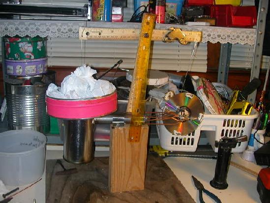
Tim Oaks
Built Dec 2006
"We first used two candles to power it
but found the sterno worked better.
We have been thinking of trying a tank
from a propane torch for a displacer cylinder instead of teh paint can
so it could
stand more heat and hold up longer. It
looks like the paint can may burn out quickly being so thin."
Tim Oaks
See Tim's engine running
Click Here
MOV File 1.2 Meg
Not a "Walking Beam" tin can, but !!!
First true Vertical Tin can engine of this style
Donnie Barnes
Nov 2006
"The
displacer cylinder is an insect spray can, 7.5 x 2.5 inches and the
displacer
is a ‘Reddi Wip’ whipped
cream can 2 ¼ inches diameter, cut down to 5 inches
high. The power cylinder is ¾” id aluminum tube
with a JB Weld
piston. RPM is about 325 using Sterno fuel. I experimented
with the
timing and seem to get
the best RPM with the power cylinder adjusted to about
125 degrees before top dead center of the displacer.
I
also tried cooling fins this time. They get warm but do not seem
to hurt
the engine speed."
Donnie
Barnes
Photo 2 Photo 3
Movie of Donnies Engine running
2.9 Meg WMV file
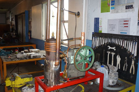
John Dewez
" I volunteer at the San Diego California Poway
train station.
We have a Rider Stirling engine that needed to be restored so
they called me to see if I could do it.
We found out that in the 1900’s they
used the stirling to pump water to the water tower so when the steam
engine
came
around it would dump 400 gallons of water in the train. We have it
working
and run your tin can stirling just
feet away for better understanding of how it
works. My next project is to get the water pump working on the tin can
stirling.
The tin can stirling runs on propane with a 2 inch flame at the end
of a ¼ inch pipe inside a reducer from a torch."
John Dewez
Tooling/Machine
Designer
Retired
from Hewlett Packard SD
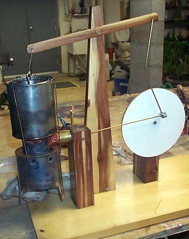
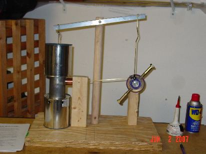
Wayne Brown
Feb 2007
Movie of engine running
AVI File
One
is 3/4 scale. My flywheels are
sidewalk scooter wheels duel ball bearing. I added weight to the pivot
to
balance the
displacer cyl. it seems to help smooth every thing out. Plus it
runs a lot longer after the heat is taken away.
Wayne Brown
Glenn Pfortmiller
Jan 2007
Photo #2
Movie of engine running
(wmv file)
Completed in Jan
2007.
The
cylinder is a brass tube about 1" diameter and the piston is corian.
The rocker arm and flywheel are also corian. The hot and cold side are
separated with a
corian base and has proven to be a good insulator. It will run
in a 70 deg F room, unlimited time,
without any cooling other than free air
cooling. It will get hot but you can still
put your hand on it without getting
burned.
Glenn Pfortmiller
Kansas
Andi from Germany
Mar 2007
I found this one
facinating enough to give Andi his own webpage. Thank
you Andi!
Andi's
page click
here
Andi's
New Engine #2 (New Style) click here New!
Oliver Cribb
Grade 7, (13 years old)
Johannesburg,
South Africa
April 2007
The bearings were taken from a
computer CD drive with a an old CD as the fly wheel weighted with nuts
around the edge stuck on with prestick.. The power cylinder is a 22mm
copper pipe and its piston made from epoxy.
Linkages are crimp lugs spaced with washers. The Displacer rod runs
through a brass bolt with an aluminium
ferrule to give a better seal. I made it in just two days during
my Easter holiday.The best speed I got from it was
about 200rpm and was very please that it ran for quite a good time even
after the heat source was removed.
Oliver's Movie
Click
Here
2 meg AVI File
Matt Engelber
June 2007
Took the scooter wheel Idea from
Wayne's project, but used an old roller blade wheel, bearing,
and axle I got from a used sporting
goods store. I removed the bearing shields and flushed out the grease
using WD-40,
then replaced the shields. The
bearings spin very freely once the grease is out of them.
Movie of Matt's engine
Jeremy Zimmermann
Dec 2007
Jeremy is from Germany!
First for 2008
Jeff and Colin's Project
"My 8 year old son and I were looking
at your web page and were inspired to begin building an engine. We
used a 3/4" copper pipe as a cylinder, and a piece of nylon turned on a
lathe as a piston. 0.032" music wire
was used as a wrist pin. The
displacer piston is made from an aluminum V8 can, which is much lighter
than
the tin version. Piston rods are made from carbon fiber rod. The crankshaft has two 'journals' to get a
larger stroke on the displacer piston. Flywheel is made from a 1/4 inch thick
rusty steel washer mounted to a hard
drive hub which has nice bearings. The height of the base is adjustable for
different height power sources.
It has been running for several hours
straight on 2 tea lite candles. No cooling jacket yet, as we are waiting
for mom to make us pumpkin pie. The pumpkin can looks to be just the
right size."
Go
Mom!
Nice job guy's!
AVI Movie of Jeff and Colin's Engine
Running
Click
Here
1.7 Meg
Tom Burns
built March 2008
After visiting your tin can stirling Engine web-site , I just had to
get out into the workshop and have a go.
I used a bean tin and a small tomato tin for the displacer, the
information on your [ site] was very helpfull, the engine runs
well on two candles.
I was a Engineer [retired] and will pass many a happy hour making tin
can Engines. - Tom Burns.
Tom's Movie
Click Here
15 Meg MOV
Doug_Mahaney
built in April of 2008
See Doug's website on this engine at
http://www.stickmanstudios.us/stirling/
with movies, and he generates some electricity with it!
No name was sent in with this one...Sorry
Built in April or May of 2008
"She started with some plans from
another site and modified based on some of
what we saw on your site.
She won several science fair awards. Here is a
link to the youtube video if you
might want to link it into your site.
The piston is your design, the
displacer cylinder is a design mix and we used coat hangers for the
connecting rods and old CD's for the flywheel.
We found that at first it would
not turn until we added at counter weight to the displacer on the
beam. "Fat kid on the see-saw hypothesis". We got about 67
RPM on the stove. It would turn a couple times when hit with the
solar beam. The angle of the heat beam from the solar collector
did not strike the bottom of the can squarely enough to get the engine
going enough.
I think we might need to try a
horizontal version or a rotary version in order to get the solar power
to really give some RPM."
UTube Video
http://www.youtube.com/watch?v=3iHmoW2zRJY
by Dr. Dinesh Anvekar, Bangalore India
Built June 2008
Innvative features:-
* Cardboard fly wheel
* Epoxy (M-seal) power piston
* Displacer cylinder made with two copper cups joined at open ends
* Gasket material and silicone sealent used for all joints
* Epoxy (M-seal) used for water-proofing and other joints
* Coke can displacer
* Bicycle spokes and flexible wire used for linkages
* Aluminium tube power cylinder
* Cycle tube brass neck and valve pin used for displacer cylinder
opening
* PC disk drive motor used for flywheel bearing
* All wooden parts are 1.5 " or 1 " teak wood battens
* Heat source is laboratory spirit lamp
Running speed: 120 rpm
Movie of above engine
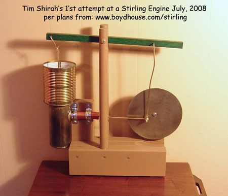
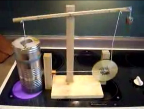
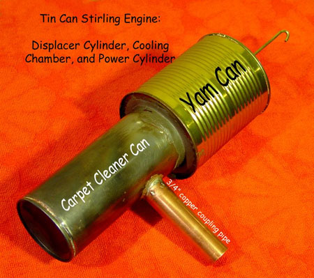
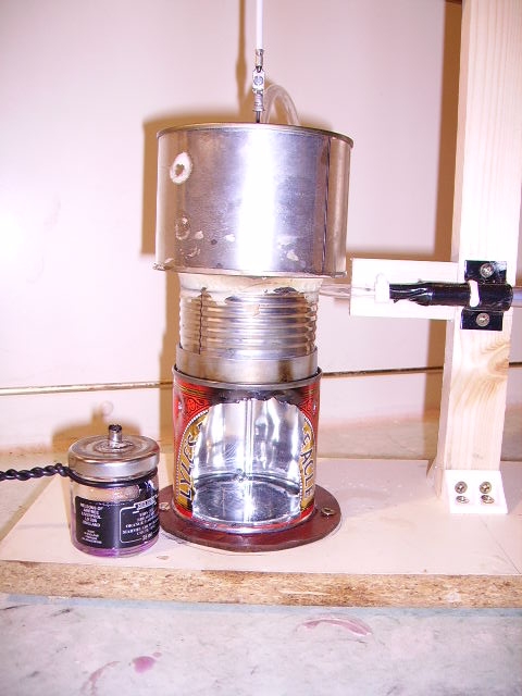
Tim Shirah
built July, 2008
I
used a can of carpet cleaner for the displacer cylinder. I had to use a
Dremel tool to remove the top since a can opener would not fit the
curved shape – it seems a spray paint can would have the same problem.
The small condensed milk can I used as a displacer piston is really a
little too tight. It sometimes touches the inside of the cylinder as it
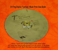
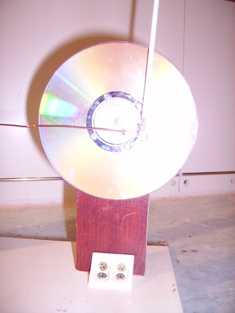
moves up and down. The door bearing I used to mount my saw blade
flywheel has too much play, causing a slight wobble. I have not done
enough to keep the heat insulated from the drive cylinder. Even when
the engine runs at its best (around 115 rpm), it stops after 2 to 3
minutes and the epoxy piston binds in the copper cylinder. I found that
JB Weld epoxy is easier to use to mount the cooling can (I used a can
of yams) than solder, as this section never exceeds 600 deg F, the
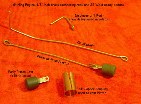
working limit of the epoxy. The copper coupling pipe I used for my
drive cylinder is used to connect 3/4” copper pipe and is therefore
bigger in diameter. It also has a slightly thicker wall than the pipe
it joins (for strength of the coupling). I bought a 12” length to cut
down for the cylinder. A shorter coupling was used to cast the epoxy
piston.
|
Additional photos (please click on the photos for a larger view of the
photo)

Video Of Engine (youtube)
http://www.youtube.com/watch?v=Vca4lY-Wk4M
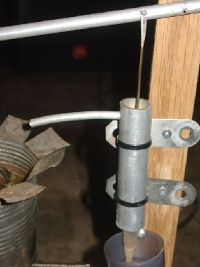
Dominic Eppolite
Dominic is possibly the oldest person to build one of
these engines.
A
note from Guy Borghi, one of Dominic's friends,
"I thought that you would be
interested in knowing that there are enthusiasts of all ages that have
built
and ran the Boyd Tin Can Stirling Hot Air Engine. My friend
Dominic
Eppolite built 3 or 4 of these engines. I have two of them which
you can
see photos of in the attachments. The unique thing about these engines
is that
Dominic built them at the age of 92. I don't think there are too
many guys
out there that have the ability to put together and operate one of
these
machines at that age. Dominic "went to be with the Lord" in May
of this year, shortly after he was diagnosed with Leukemia. He
was a
resident of the Quarryville Presbyterian Retirement Community which is
located
in Quarryville, PA.
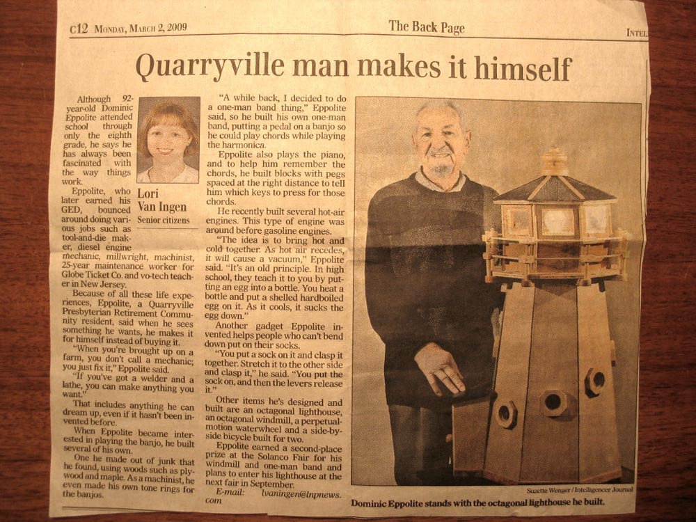
Dominic loved to build things and many of them were his own inventions.
Just
this past March 2nd, 2009, the Lancaster Intelligencer Journal
published an
article about Dominic's life. I also included a photo of the
article
clipping in one of the attachments, where he is shown standing by a
lighthouse
he built. The article makes reference to several of the projects
Dominic
constructed and/or invented.
|
These are works of art!
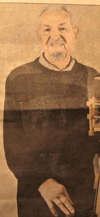
A
92
year old man who shared in the enthusiasm created from building the Tin
Can Engine.
Dominic Eppolite (at the age of 92) Built February
2009.
Read story about Dominic Click Here
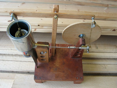
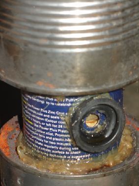
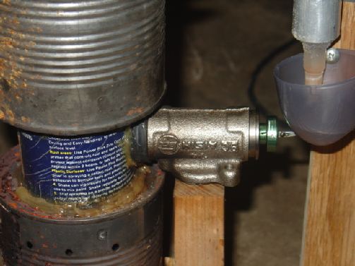
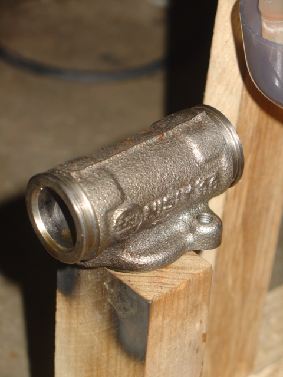
Rob Kay
built Aug 2009
New Zealand
|
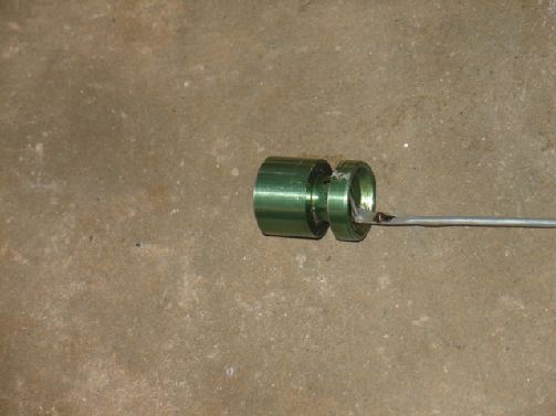
I
used a brake piston (green
anodised!) that fitted beautifully inside the 25mm copper tube. I used
a tennis
ball can for the displacer and a small baked bean can for the displacer
piston
- it was hard to get the beans out! After the first few runs I used a
small
bearing race for the flywheel and the improvement was great. As you can
see I
used penny washers for the pivots of the rods as I found it quite
difficult to
form the end of the rods to a good shape. I did just flatten and drill
a
couple. I initially soldered legs on to the firebox but the solder
melted so I
riveted some on. I run the engine on methylated spirits (denatured
methyl
alcohol) as Sterno is not readily available here.
Rob
Kay
Nelson,
New Zealand
|

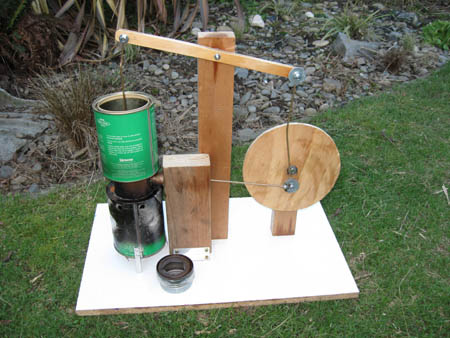
Rob Kay
built Aug 2009
New Zealand
|
I used a
brake piston (green
anodised!) that fitted beautifully inside the 25mm copper tube. I used
a tennis
ball can for the displacer and a small baked bean can for the displacer
piston
- it was hard to get the beans out!
After the first few runs I used a small
bearing race for the flywheel and the improvement was great. As you can
see I
used penny washers for the pivots of the rods as I found it quite
difficult to
form the end of the rods to a good shape. I did just flatten and drill
a
couple. I initially soldered legs on to the firebox but the solder
melted so I
riveted some on.
I run the
engine on methylated spirits (denatured methyl
alcohol) as Sterno is not readily available here.
Rob Kay
|
Dale Hoerner
Built Dec 2009
Well, I just had to send you a photo.
The
darn thing runs.
The power piston is epoxy. The fire box is a spaghetti
sauce can. All the con rods are 3/32 brass rod. The main
bearing is
a sleeve and rod from an old DVD drive (not the motor).
With one tea
candle it runs at about 60 - 75 RPM depending on how well adjusted
everything
is. I have a little too much friction in the power piston and in
the
displacer sleeve. But it sure was exciting when it ran the first
time!
Dale Hoerner
|
Morteza &
Mohamad Salimi
Built September 2009
Jan From Denmark
A few Links (Movies and Photos)
http://s280.photobucket.com/albums/kk189/speedless/Stirling/?action=view¤t=PICT0035.mp4
http://s280.photobucket.com/albums/kk189/speedless/Stirling/?action=view¤t=PICT0027.mp4
http://s280.photobucket.com/albums/kk189/speedless/Stirling/
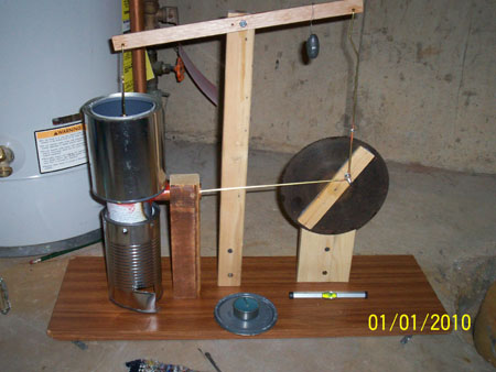
Keithe Campbell
built 2010
|
cylinder- copper, honed
power piston -made on lathe,.002 under
cylinder
bearings - from old VHS player
push rods- bicycle spokes
wrist pin- from VHS player
heat source- can of sterno at bottom
water in top can,
displacer piston - made from balsa .
|
timing
adjustments - servo arms from RC
equipment
Mike Mathrole
Built 2008
I stayed
pretty close to the plans but I cheated
a bit and used my metal lathe to make the piston. I also used ball
bearings on
the main pivot for the walking beam, the wheel and the rod connection
on the
wheel, the other pivots on the walking beam are brass bushed for smooth
operation.
|
Our "Newest" Additions!
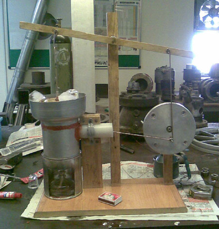
Tony Cunningham
|
I built this engine sticking strictly to
your design
criteria except for the following points:-
1. The top of the displacer cylinder is
not soldered on.
I have used a rubber seal instead. This allows access to the displacer.
2. I have also used a rubber "O" ring
seal
between the water jacket container and the displacer cylinder.
The water jacket container is smaller
than your original
design, only because a larger paint can was not at hand at the time.
Running
time is restricted, confirming your design criteria. I have inserted
folded
aluminium strips to dissipate some heat.
3. A picture is attached and any other
differences are
purely aesthetic.
It runs very well, easily achieving
100-150 rpm with a
small spirit burner. I lack movie making skills but I have managed to
put a
short video on youtube, should you be interested in seeing one example
of your
work. This can be found here : http://www.youtube.com/watch?v=fYsOzo-VhjM
|
John Gardiner
built early 2011
Had scrap
aluminum
angle lying around. I love working with it... so made the structure
from it.
Made all the linkages to your exact dimensions from 1/8 welding
rod, except for
the small 1 1/2 inch link (joining the walking beam to the displacer
rod). This, I made from some scrap aluminum I had on hand.
I drilled
several
adjustment holes in it, then used a small bolt to connect to the beam.
However I added a REGENERATOR which improved performance significantly.
Here is
what I did.
The displacer was made from a a PVC metal dope can...easy to find in
Home
Depot. I cut the protruding top off and soldered on a new tin can top.
Next I got aluminum window screening 3' x 7' roll. I did not remove it from its
plastic packaging film.... but rolled the film back
only about 4" from one end.... measured the displacer length...taped
the
screen either side of my intended cut and cut it (with a cut off wheel
in a
4" Makita grinder). Then I wound it round the periphery (outside
surface)
of the displacer...had to cut maybe 2 turns off to allow it to go
through
lip...sealed the free edge with JB, taped it til it set, then secured
it with
wire, top and bottom, to displacer rod and away it went.
Improved performance immensely!!!!!! |
Rob Johnson
built Summer 2011
|
Continues
to run
sweetly...and have turned on a few friends who are also
"building"....
What I've
done that
works incredibly well is to use what's called piano wire (very very
small
diameter steel rods available at hobby shops for about 25 cents for a
three foot
length) instead of the 1/8 inch stuff.
Then instead of the bolt, I've
drilled a 3/8 inch hole in my top and shoved a black rubber stopper
(available
at the hardware store for about forty cents) up from the inside.
Once in,
it forms a perfect seal and is almost unremovable. a tiny hole
drilled in
it for the piano wire and a touch of 3 in one oil and it's virtually
frictionless and completely air tight.
My JB weld piston is a great fit
(after quite a while of very careful gentle sanding). Next time I
would
prefer the aluminum rod thing though...
|
Way cool looking Walking Beam Stirling Engine!
Bob Hammell
Built in Summer of 2011
Dan Pickard
Built in Summer of 2011
Vikram Vicky
From India
Built in Summer of 2011
A lot
of people have made
this
engine.
If you have one, please email
me and I would love a photo to use on the page
Variation
on a theme!
Not "Tin Can Walking Beam" Engines
But still "Master Pieces"
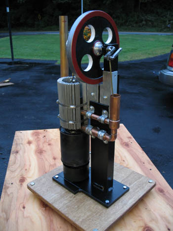
John_Schedler
built built
Aug 2009
|
-Base
measures 14" X 14"
-Engine stands 24" high
-This engine runs off of Chafing Fuel.
-All joints are silver brazed
-There is a regenerator in this engine.
-The crank eccentric has a hole in it to accept a drive shaft and will
have a
small fan blade fitted to it.
-The piston is machined and measures 1 1/16" in diameter.
-Stroke is 2 3/8"
-Displacement cylinder is a Lysol can with standard tomato paste can
inside.
-Air-cooling provided by aluminum mat slats secured by hose clamps.
Cooling
capacity far exceeds needs.
-Running RPMs: 140 - 160
This engine will run for approx. 3 hours from one chafing fuel
container.
Build time is about 55 hours. The tolerances are close and this
engine is
extremely quiet. I lube it with sewing machine oil.
John Schedler
|
Additional Photos
Photo #1 Photo #2
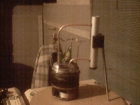
Richard Dales
Built Jan 2008
|
Power cylinder is 15mm copper water pipe.
Power piston is JB Weld epoxy (tolerates
c.350 deg C?)
Crank is coat hanger wire Flywheel is a CD, centred onto the crank
using screw
top from toothpaste tube. A small coin balances the flywheel against
the weight
of the displacement cylinder.
Expansion and displacement cylinders are
aluminium
Guinness cans.
Small bits of steel from top of a baked
been tin were
used for the three points where wires pass through holes.
The three Aluminium cans are cut with
ruler and Stanley
knife, or scissors where appropriate.
By rubbing the inside edge of the cut
cans hard against
my vegetable chopping board with a teaspoon I found the each can could
be
easily pushed inside the next. A tiny bit of JB Weld ensured a good
seal.
Lubrication used was olive oil, but
sowing machine or
hair trimmer oil would have worked better.
Richard Dales
|
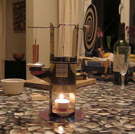
Matthew Shippee
Built 2009
|
While
this is not a walking beam stirling, I could never have gotten it
working
without info from your site and plans.
There
are also several videos on youtube (mrweaseluv) that you might like to
link to (3rd and best video will be up tommorow with a little luck)
And a word of advice to new
modelers, a ball bearing in matching bearing tube
makes a great airtight power piston :D (attaching the bearing to the
rod is the
fun part hehe)
Matthew
Shippee
|
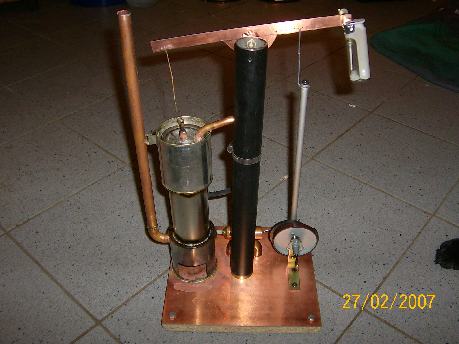
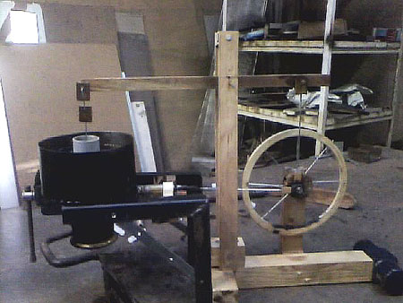
Paul Maciulaitis
New Zealand
|
Here's my bigger version of your tin
can engine. It still needs refinements like better cooling later on.
The power
piston cylinder and crank was a 2hp briggs and stratton
i fitted
teflon gland packing for rings and drilled out the spark plug hole and
fitted a
1" pipe fitting. The displacer is an old air tank and the firebox is a
peice of stainles chimney almost all bearings are roller it goes about
50/60
rpm.
Heres a link of it running on kindling wood http://www.youtube.com/watch?v=6tHtlx3VbqM
anyway thanks the small one is still going good
Paul Maciulaitis
|
We're Cooking Now!
Magnificent Works of Art!!!
