Boyd's Tin Can Stirling's

Hot Air Stirling Engine Web
Page
Hot Air Engine, Stirling
Engine,
External Combustion Engine, Stirling Plans, Hot Air Engine Plans,
Stirling
Walking Beam Engine, Sterling Engine (oops!)
www.boydhouse.com/stirlings
"True"
Horizontal
Tin Can Stirling Engine
Most
tin can engines either have their displacer piston and power piston in the
vertical posision.
Or as in the walking beam tin can it has one in the vertical posision
(displacer piston) and one in the horizontal posision (power piston).
This is the first tin can engine to place both the displacer piston and
power piston in the horizontal posision.
Making it a "true" horizontal tin can stirling engine.
Disclaimer (sort of )
| I would build the "Walking
Beam Stirling Tin Can Engine" first if this is your first engine.
There
is more details and hints that are very helpful to the first time tin
can
builder.
If you have already build a working ,
then
you will be able to figure out how to build this one. Close to the same
as the "Walking Beam Stirling Tin Can Engine" with a few major changes.
You're on your own!!
|
This projected started with a "Walking Beam"
engine
displacer cylinder ,power cylinder,
and displacer I started and decided not to finish.
Instead I decided to make a "true" Horizontal engine out of it.

Reworked displacer piston. Note rod is steel not brass and
goes through the displacer and out the bottom 5 1/2".
Brass rod sags too much and a steal rod eliminated this problem.

View of top bearing of Displacer Cylinder.
Same as the original "Walking Beam" engine.

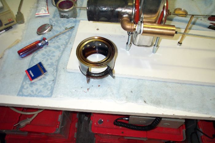
Reworked displacer cylinder. Note brass tubing silver soldered onto
the bottom to help support the displacer piston.
(This is not the finished design. See below)

Displacer piston is slid into the displacer cylinder and top is
then added
(This is not the finished design. See below)

Top is then soldered on
(This is not the finished design. See below)
Changes !!!

| After some consideration, I decided
to make
a few changes.
1) On the bottom or to the left I
removed the
brass tube and replaced
it with a brass bolt with a 1/8" hole
down
the middle just like the top bearing. I was concerned with the extreme
heat melting the solder and releasing the brass tube bearing. This
"bolt-in"
approach removes this possibility.
2) I made a temporary brace to help
hold the
power cylinder straight and true while soldering. I wired this on.
|

Temporary brace and wires were then removed.

Displacer cylinder was installed and top was soldered on.
Painted with high temperature black paint.

Another good photo of the "new" bottom bearing.

Good photo of the top bearing. Same as the "Walking Beam" Engine.
Phase 2
 Some
alterations were made.
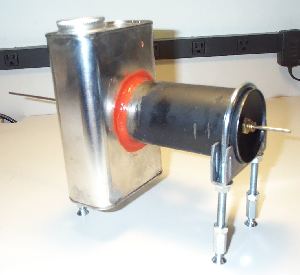
The old copper
pipe was removed and a new style power cylinder and piston was installed
.You can see
the new style cylinder here
Some
alterations were made.
The old copper
pipe was removed and a new style power cylinder and piston was installed
.You can see
the new style cylinder here
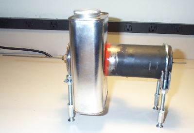
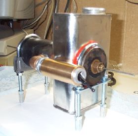
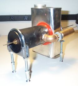 I added a 90 degree elbow fitting to
the back of the new cylinder
I added a 90 degree elbow fitting to
the back of the new cylinder
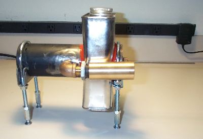
The water cooler tin can was
hole sawed out and fitted on the displacer.
Then it was attached using red hi temp
silicone sealer. You can get this at any auto parts store
 I used a U bolt from Orchard Hardware
for mounting front and back.
I used a U bolt from Orchard Hardware
for mounting front and back.
Copupling nuts at the bottom with flat head machine screws will mount
from under the wood board when mounting.
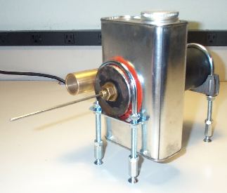 Picture of front U bolt setup
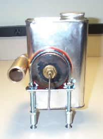 Ready to mount to a board.
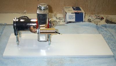
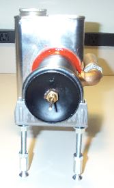
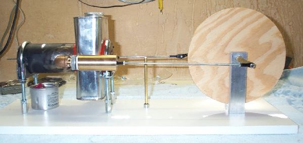
Here it is mounted to a shelf board.
Close up of the power piston just hanging out just a little.
I used a rod end from a hobby shop on the power piston.
Now for the fly wheel!
Phase 3
Almost done. In this phase (at the end) I fired it up. It would make
about 3 to 4 cycles and then stop.
More on that later!
I used tie rod ends from RC planes to make the connecting rod
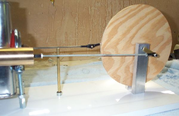
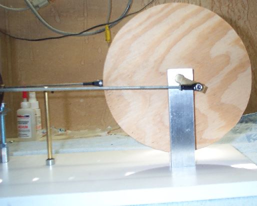
I used RC rod ends and clevises to make the displacer rods. I had to
support the rod coming out of the displacer
cylinder with a brass rod. This made the rod go in and out easier
without binding.
A better view of the same rod
As I said earier, I fired it up and it would go about 3 or 4 cycles and
then stop. I removed
the piston rod from the flywheel crank and turned the flywheel around
creating "cycles".
The piston would push out and pull in just as it should, but I feel it
should have a little more power.
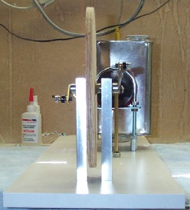
Problem?
I think the main problem is not enough heat getting to the rear of the
displacer cylinder.
As you can see I have no "hood" around the displacer cylinder to direct
the heat evenly around both
sides of the cylinder (outside). I think if I fabricated a hood it
would heat more evenly. I was able
to get more power by moving the Sterno can back and forth or from side
to side. This heated the engine on
both sides more, but even would be better. (no I didn;t use the
entire can of Sterno. That is an enpty can with the lid on it.
The Sterno was placed on top of that to get the fire closer to the
cylinder.
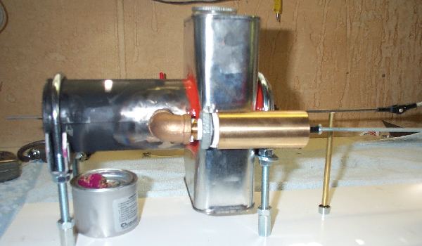
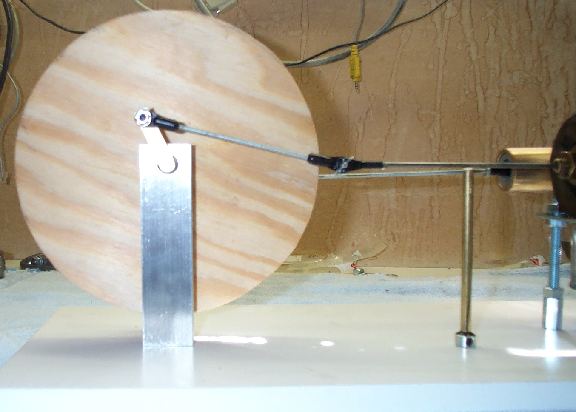
The second proplem is......Tha big honking "U clamp" in the rear. I
think it might be sucking up a lot of heat. Sort of like
a heat sink. I think I might move that forward all the way to the water
tank as close as possible. That might help a bunch also.
Still over all. 4 cycles is not too bad for a first attempt!
Phase 4
The
Final Phase?
"I've got to have more power!"
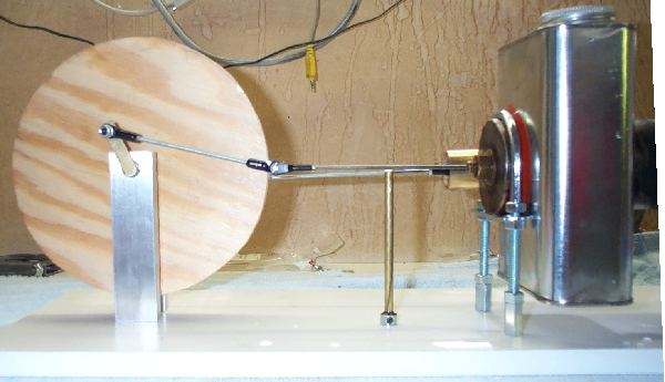
OK, moved the mounts (pipe clamp) forward in front of the power piston
exit and made a fire box.
The fire box was made from another can (like to stay with the program)
and installed.
Ran great for about 2 to 3 minutes then everything broke loose....well
exploded to be exact.
You will notice the small can of sterno on the left of the photo above.
That can had it's lid on
and sterno on top of it to place the fire closer inside the firebox. Very bad idea!
After running about 2 to 3 minutes that can heated up (DUH!) and
exploded. That is why the lid is off
and the fire box is turned a little sideways. Didn't even see that one
coming! Can was still on fire be it almost out.

Notice I thoiugh about removing the cap of the water tank. I though to
myself.....
better remove that cap, don't want this thing building up pressure or
steam and blowing apart!
Almost had it right!
Firebox removed from rear of engine
Still it ran for some time there. I need to work on the timing a little
and a new way to deliver the fire into the fire box.
That's it! I don't see a PHASE 5!
Return
to main page
© 1999-2003 Darryl Boyd, All rights reserved
Comments can be
directed to