OK so I tricked you into taking a
look at a "computerized" Stirling engine.
Actually some of the engine is made from several computer parts
recycled from a couple computers. The intent was to use as many
"computer" parts as possible.
More so than that, I really was trying out a few new
techniques that I though might work and would be easier to accomplish
by beginners. Plus I was trying out a few new ideas for the horizontal
tin can stirling under construction.
I will discuss these
new technique under each photo below.
As for how the engine ran well.................It suffered catastrophic
failure after about 50 revolutions. It ran good when it did run but one
of the
new techniques I used failed. The displacer piston
separated from the rod that controls it. It then came to an
abrupt stop. (more below)
However many new techniques that were used worked quite well, just not
all of them!
|
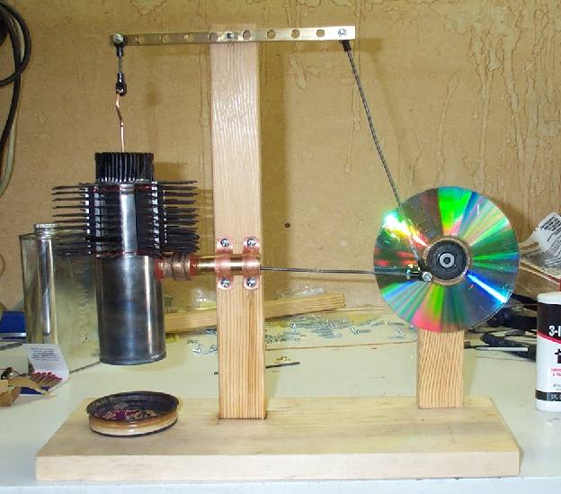
This is not intended
as "PLANS" to build this engine.
On the left, the displacer cylinder.
The top was made from the heat sink from a computer CPU. That is the
piece that cools down the main computer chip in a computer. (more
details later)
Also around the side is another heat sink form another computer.
On the Right, the fly wheel. Made from a CD disk (compact disk). The
main bearings on the flywheel are from a CD player along with the hub.
|

| This is a detail photo drilling out a small
brass "stand off" that supports the main "mother board" in an old
computer. This piece will become the brass rod guide on the top of the
displacer cylinder. |
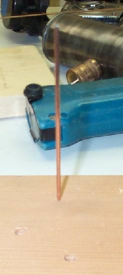
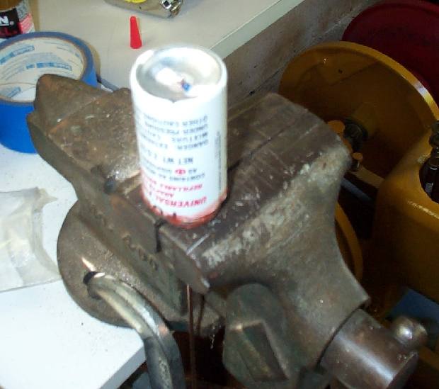
These photos are how I squared that brass
rod guide to the top of the displacer cylinder.
I took an old heat sink (as stated above) and drilled through the
middle of it with a hole saw. That made it close to the size of the can
I chose for the displacer cylinder. I then sanded it to fit tight in
the top of the displacer can.
I drilled a hole in a wood board the size of the rod I was using and
pushed a piece of the rod in it (see photo on left)
I lowered the brass guide down the rod. Then I dropped the heat sink
over it.
Here is where I went wrong. Although this is not the piece that failed
in the end, it is the same technique used that failed. I used CA glue
(medium set super glue) to attach this guide to the heat sink.
|

I
have build several steam engines and
they call for using this glue to hold on some of the parts. I wanted to
see if this might be a good alternative to soldering as on my "bigger"
stirlings. It is a "medium" set CA glue. In other words, it doesn't
setup fast like normal super glue until you hit it with an activator.
Then it sets. This gives more time for installation. (more later)
This technique worked very well on the top of the engine, but I would
not use it down lower to the "hot" side of the engine as you will see
later why.
|
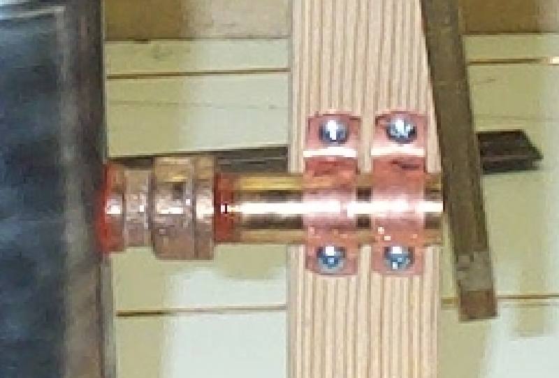
This is the displacer cylinder. It was a
WD40 small spray can. Instead of trying to solder on a power piston
cylinder I decided to try to "bolt" it on some how. I selected
(from left to right in photo) WD40 can, 1/4" brass bushing, 3/8" to
1/4" brass bell reducer, a short piece of 3/8" brass pipe nipple (i cut
of the threads on one end). I ran a 1/2" drill bit on a drill press
(you could use a hand drill) to ream out the inside to 1/2" for the
piston.
|

I assembled these item and used high temp
silicone around all the joints. This silicone can be bought at any
automotive store. This technique can be used on the larger tin can
engines also as it worked very well and the silicone never had a
problem with the heat.
Two techniques that worked well so far.
|

Photo of what it looked like inside the
displacer cylinder before adding the displacer.
|
The displacer:
Made from butane canister that is used to refill butane lighters etc.
Cut down and the top portion "glued" onto the bottom using the Hi temp
silicone. This worked well also and was not the problem (not yet!).
|
I drilled out the top and the bottom of the
butane canister and inserted the rod all the way through it. I then
used CA (super glue) to hold it onto the rod.
This is the joint (and the one below) that let loose when the engine
got too hot. The CA glue could not take that much heat.
|
This is the bottom of the the displacer
where I also used the CA glue that failed. It turned out to be
catastrophic because when it failed, the displacer fell of the
end of the rod inside the sealed displacer cylinder.
|

Here is the entire unit mounted onto the
engine. The top heat sink was glued on using CA glue. Again this worked
out OK. Notice I used copper pipe clamps to hold the displacer/power
cylinder on. This is another new technique that worked great.
|

The Power Piston:
Made from a 1/2" diam. capacitor taken from the power supply of the
computer. It was gutted and the end cut off to form the piston. A
small piece of brass flat stock was bent in a small "L" shaped and a
small hole drilled in one end. The other end was inserted into the
piston and it was filled up with JB Weld. This was a new technique to
me and worked out quite well. On the end of the rod was a small radio
controlled airplane rod end for swivel.
|
 Drawing of capacitor
 Preparation of capacitor to make
piston
Preparation of capacitor to make
piston
Close up of the mounting of displacer/power
cylinder.
|
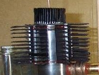
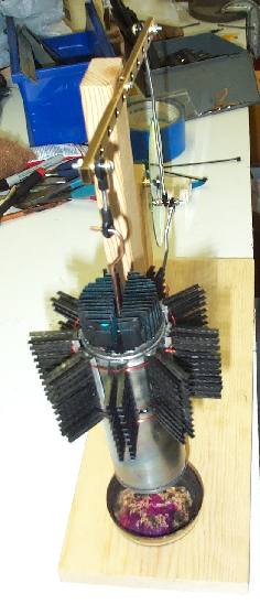
On the top of the displacer cylinder was
another heat sink cut into small sections and CA glued to the side of
the displacer cylinder. The were also wired on. This is a technique I
wanted to try and use on the horizontal tin can engine coming next. It
proved to work out quite well and solved a big problem (cooling) of the
horizontal tin can engine.
|

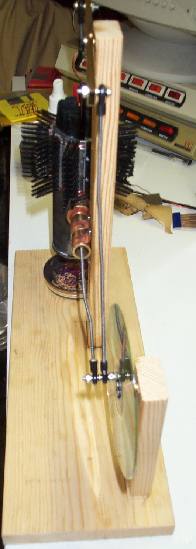
Close up of the walking beam.Taken from a
support rail of a larger main frame computer and re machined. All the
bearings and joints on the rod were radio controlled airplane rod ends
from the local hobby store.
|

| Another look at the flywheel. Made from a
CD disk (compact disk). The main bearings on the flywheel are from a CD
player along with the hub. |
The completed engine just before it's
second (and last) attempt to start it. After making some
adjustments from the first attempt (would only run a few revolutions
then stop) a second attempt was made. I stoked up the sterno (maybe too
much!) and fired it up.
It started to run quite
well and I was enjoying it when after maybe 50 revolution it came to a
crashing stop. The rod going down into the displacer had separated from
the displacer inside the displacer cylinder. Not much chance of repair
as the top of the displacer cylinder (top heat sink) was CA glued on
and not removable.
The engine was finished but......
Parts such as the bearings (rod ends) and side heat sinks etc. are
being reused to finish the horizontal tin can stirling engine.
I hope the horizontal engine works out better!!
Well.....Back to the drawing board!!
|
Return to the Stirling
Web Page
Click
Here
|