|
8’ Loop
X-tal Set
by
Josh Young
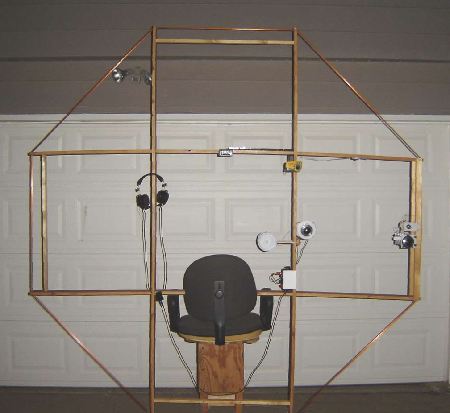
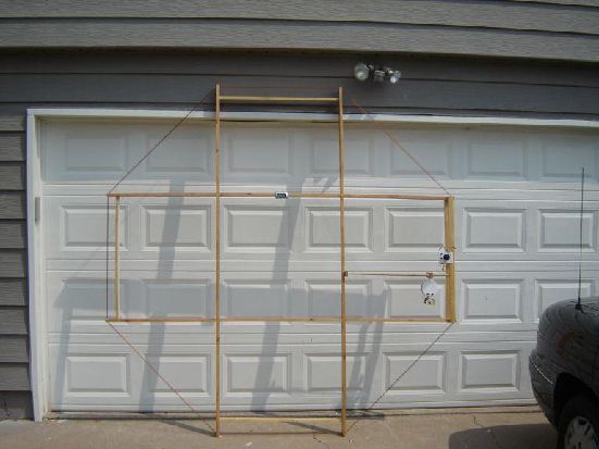
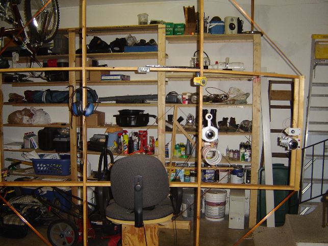
Overall size, and how the set looks when it
is in use on it’s homemade chair/stand.
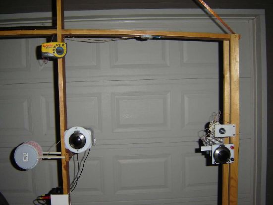
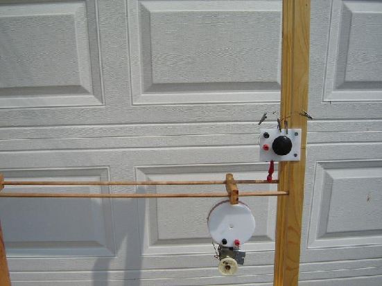
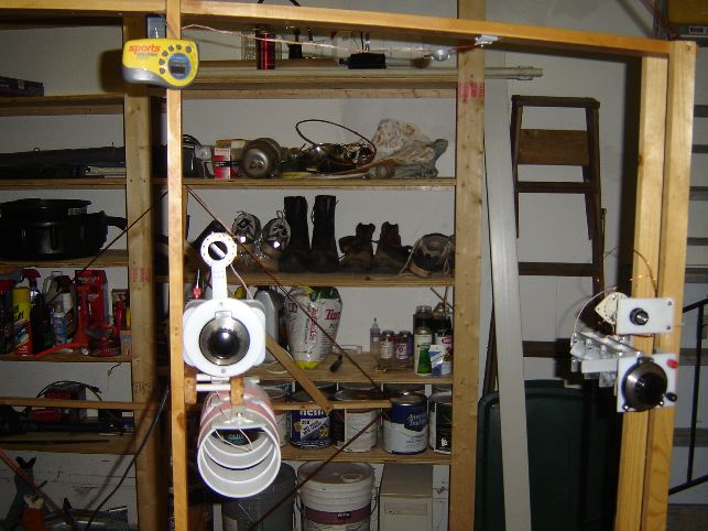
Up close of the “Control
Center”.
You can see the Series/Parallel
switch for the main loop on the right hand side.
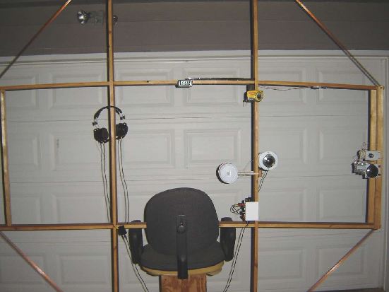 Notice the Digital
Spotter Radio, LED Light( above the VC’s on the horizontal spreader),
Clock, and Slide-In Transformer box holder.
|
8' Loop Crystal Radio
by Josh Young
About eighteen
years ago my
Grandfather introduced me to crystal radio fun.
He told me some really neat stories of receiving long distance stations
with no batteries or power. Ever since
he bought me my first Radio Shack Crystal set I have been hooked.
I have been experimenting and tinkering with
them off and on for about 16 years, and I am continually amazed at
their
performance. I can’t say exactly when it
happened, but along the way somewhere I got interested in Loop
X-tal sets. My first Loop
made was a “X” frame made from some cheap wood and a scavenged Variable
Capacitor from an old Heterodyne AM radio.
It was about 1 foot per side, and had about 15 turns to resonate the BC
band. It was a very poor performer, but
gave me interest to keep on advancing.
The current set I have worked
up to is the 8’ Octagonal double tuned
X-tal set. I have included a Led light, a Digital spotter
radio, Ceramic insulated Silver Plated VC’s, and some nice calibrated
reduction
tuning knobs. These additions have made
for some pleasurable Dx-ing. It seems to
be a real performer, as I have logged over 85 stations at night, and DX
at 1400
miles. There are certain aspects that have drawn me
to loop sets, some include: precise station direction finding,
portable, deep
signal nulls, low noise signal source, neat looking, straight forward
construction, no dependence on external ground/antenna, very good
signal
gathering capability, and very high Q set potential.
I choose the Octagonal shape because it was
easily constructed, and gives near Round-Loop results. This
particular set is made out of 1x3x8 cheap lumber, has been stained and
sealed
to keep it looking fairly nice and to preserve longevity. Wood
was used because it was very easy to
work with, and was light weight.
I used a dado blade to make
the “Slots” in the wood frame material that allows it to be
assembled.
I also used the dado blade to produce the
slots on the ends of the frame that allows Styrene insulators to be
inserted. This would also be a good time for me to
mention a problem I have encountered with my current Loop. One of
the Horizontal spreaders now sags due
to the weight of the Variable Capacitor on it. It would be wise
in the future to support the
V.C. on the Tuned Loop from the interior of the Set as opposed to the
exterior.
Since the function of the main Tuned
Loop is to gather/reject signals it is necessary to build it in a
manner to
preserve all the “Q” possible. Keeping
in mind the afore mentioned, another aspect I tried to keep in mind on
this
Loop Radio is to minimize metals near the Loop. Metals in
proximity to coils have been shown
to distort reception patterns, so where ever fasteners were needed I
tried to
use less lossy materials. Fasteners
considered should include: brass,
stainless steel, or nylon.
|
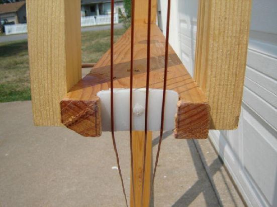
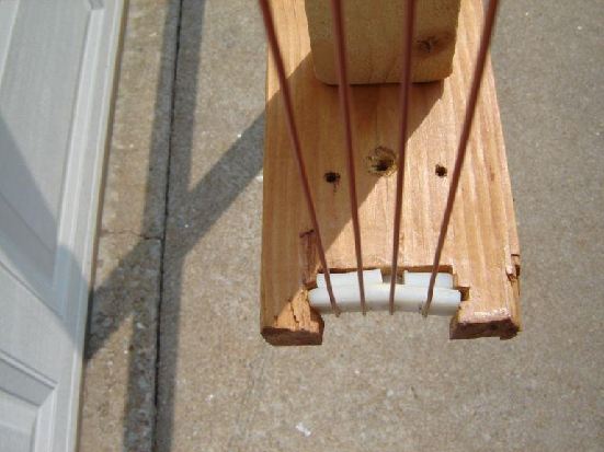
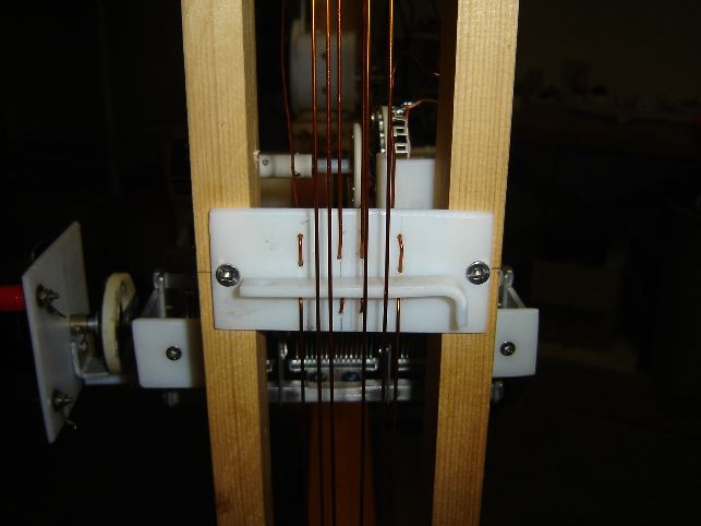 Wire termination
insulator detail.
The Styrene piece that is turned on edge is used to maintain wire
separation.
|
In past articles on
crystal
set design, I had seen some information about insulation materials and
their
benefits when used properly on components that are exposed to RF
energy. One of the materials mentioned was Styrene,
which usually is a white colored plastic and is very easy to work
with. Styrene is used in many ways, one of which is
for drain type plumbing. Genova products
is one such company that makes Styrene fittings, and should be easy to
locate
at local plumbing supply houses. Since
Styrene has been said to work well for RF insulators I thought I would
try my
hand in using it. As you can see in the
photos, the 18 gage wire never touches the wood directly, to help
minimize RF losses. The wire is suspended above the wood by the
Styrene insulators, and has yielded very noticeable results.
Usually the Styrene purchased from local
plumbing supply companies comes in fitting which are sometimes
curved. One way I found to straighten the rounded
pieces to make them into a more useful shape is to cut a certain amount
out of
the fitting, dunk it into boiling water and straighten it to the
desired
shape. The Styrene needs to be heated
by the boiling water a few minutes, and then can be easily
formed. I made a flat Stainless Steel jig to flatten
the Styrene to make the flat pieces seen in the photos behind the
Tuned-Loop
knob. My jig is two pieces of Stainless
Steel about 5”x 5” w/ small holes in the corners to facilitate screws
for tightening
the two halves together. I place the
Styrene to be flattened in the jig, insert screws w/ nuts into the four
holes,
place it in boiling water, and every couple minutes pull it out of the
water to
tighten the screws to flatten the Styrene.
This may not be the best or easiest way of making flattened pieces, but
it has worked well for me.
The wire I have chosen for
this particular tuned Loop was 18 Gage solid enamel
coated wire. I choose this particular
wire because it was the largest diameter solid wire I had
available.
I actually ended up reclaiming it from a
large power transformer! The next time I
create a new monster Loop, I will seriously be
considering high count Litz. There has
been much speculation that high count Litz wire may yield better
results on a
loop-type set as opposed to a standard Antenna/Ground type set. I
just haven’t saved up enough money yet to
give it a spin, but with any luck I will eventually. After
perusing Ben Tongue’s web pages I
decided to attempt a Contra-wound winding scheme on the main tuned
Loop,
and have noticed good results. Information on the Contra-Wound
winding
scheme can be found at www.BenTongue.com.
I also tried to maintain approx. Ľ inch spacing between adjacent
turns, in
order to minimize stray capacitance. The
wire ends also terminate into the Styrene insulators mentioned above,
but other
insulating materials may be used with good results. It is
also necessary to get the turns as tight as possible to restrict
movement, as
slightest movement of the wires can cause frequency variation or other
undesirable results.
I
choose to use a double tuned configuration to reduce direct loading on
the main
loop, which can increase selectivity and sensitivity. When using
a double tuned circuit one can
distance the two coils to reduce coupling, although other electrical
configurations could yield similar results.
The “Hobbydyne” type circuit is one I have in mind that could be
interesting to try when directly connected to the main tuned
loop. I haven’t tried it yet, but probably will
soon. I have often wondered if it is
better to reduce the coupling by physical coil separation, that way the
receiving
pattern is not distorted by the extra components it would take to
electrically
reduce coupling. Only time, and
experimentation will tell.
I currently use RCA Sound Powered phones
with a UTC-015/Bogen STM Impedance
matching circuit w/ a “Benny”. The two
diodes I have had excellent luck with are (1)1N770P10, and (2) HP
5082-2835’s
in parallel. Those have given me the
best weak level sensitivity, but I haven’t tried all that there is to
try. I am still learning, and it seems as my set
progresses with better VC’s and wire etc. I also find that the best
diode
changes from time to time.
I have attempted to give a general synopsis
of my Loop set. It is an ever-changing design, and gets
better all of the time. Much of this
information was learned on the Rap & Tap, and spending time on the
many
great websites doing research. I need to
give much credit to all the helpful guys on the Rap, they are
great! Hopefully this will inspire some to
reevaluate Loop performance, and possibly
build models with their own hints and wrinkles.
I know that I am always amazed at how well it
performs. Enjoy, and have fun!
Josh Young
|
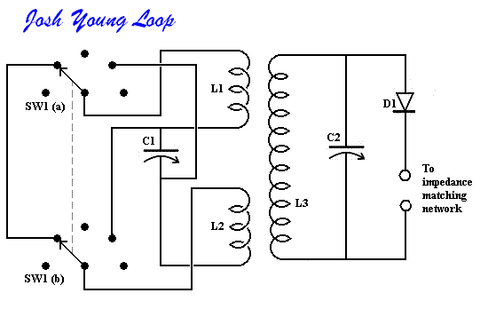
|
Parts List
L1
Coil 3 turns (contra wound to L2) part of main loop
L2
Coil 3 turns (contra
wound to L1) part of main
loop
L3
Coil 420/46 Basket Weave Litz
C1
Variable Capacitor 15 - 400 pf
C2
Variable Capacitor 15 - 400 pf
D1
Diode 1N770P10
|
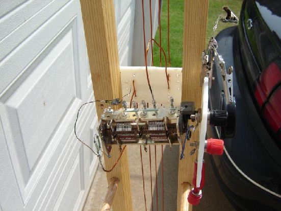
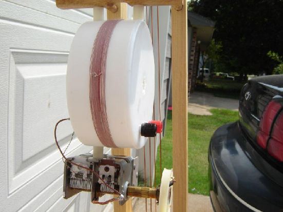
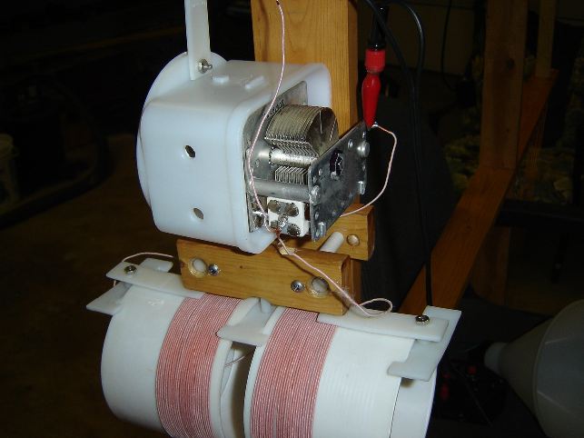
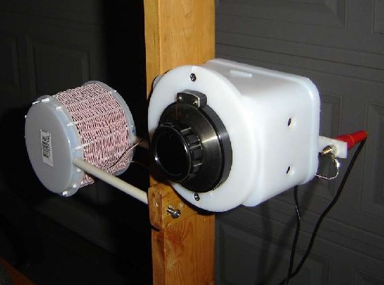 Detector Cap/ Basket Weave Coil assembly.
Vernier calibrated knobs are
used to make tuning nicer. Capacitor is protected inside the
Styrene drain spout adapter.
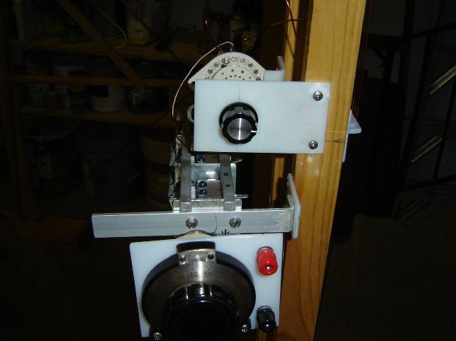 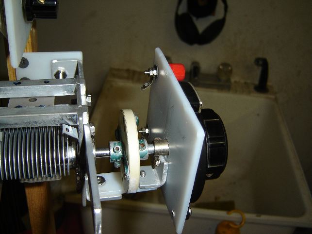
(left side photo)
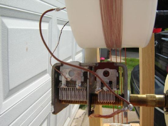
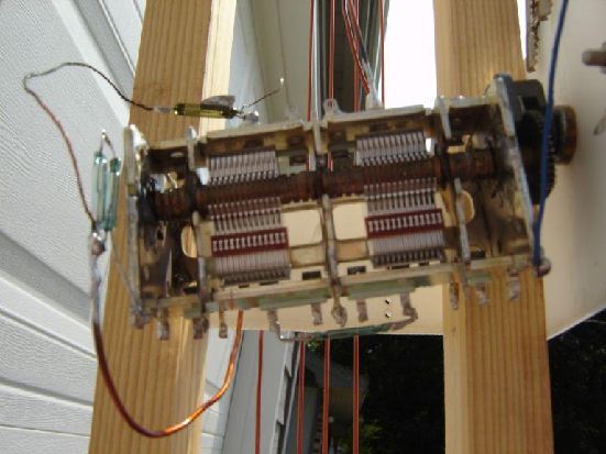
Shows main Loop Tuning VC, and Main Loop Series/Parallel switch. (Right
side photo) Also shows the
1/4 “ shaft insulator as it goes into the Vernier dial to help
with any hand capacitance. |
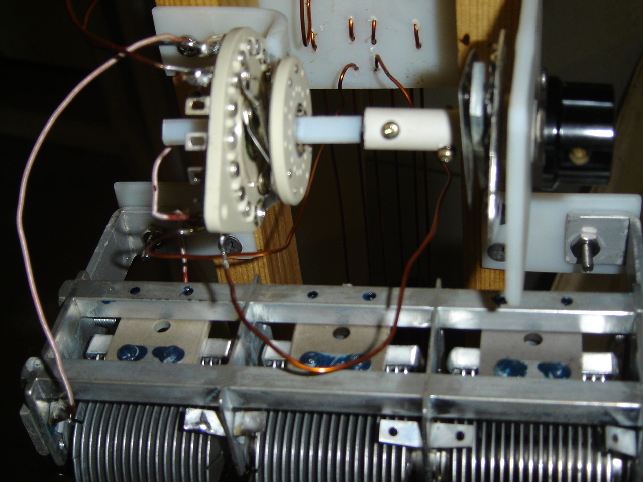
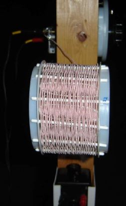
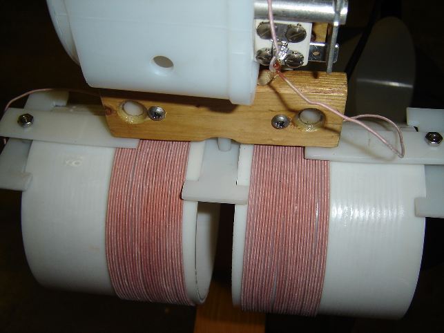
| (left hand photo) The main Loop
Series/Parallel selector switch. (right hand photo) Basket Weave coil with form holder.
|
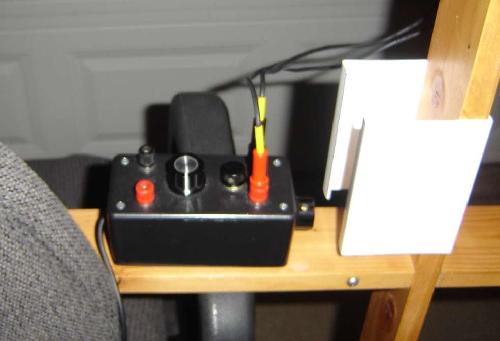 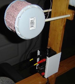 Photos of matching transformer
unit and holder (right side it is in it's holder)
 LED push button
Photos of the original Loop Crystal Set
Sometimes it's fun to see the progression a a set
|


