Tuggle Two
The Modern Radio Laboratories®
(MRL®) #39 Crystal
Set --
Modified

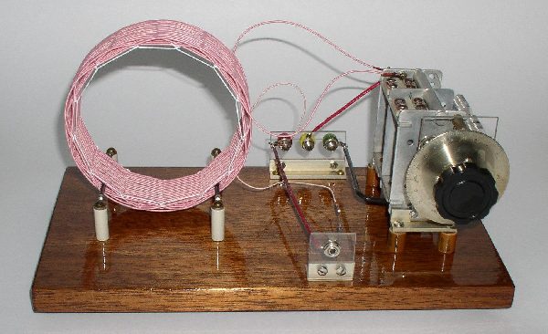
(Please click on the image above
to see
a
more detailed photo of the radio. It is well worth it!!)
By Mike Tuggle
Written 05/21/04
One evening, while perusing MRL®
Handbook-17, which I hadn't done in some time, the MRL®
#39 circuit hit me between the eyes ! This circuit has some
amazing
similarities to, and differences from, the Australian Mystery Set.
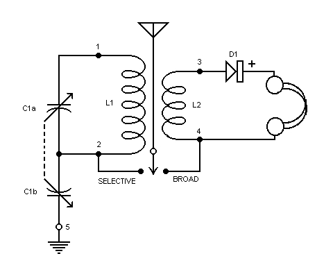
The original MRL® #39 had the
antenna attached
to point 3. Consider points 1 through 5 on the schematic: there are 20
possible ways to attach antenna and ground to these points -- 25, if
you
also consider antenna alone. Using a prototype set, I looked at all 25
and found that point 5 consistently was the best ground, and points 2
and
4 gave the best Selective and Broad tuning antenna connections. That's
for my particular antenna and ground, anyway -- the point here is,
experiment
and see.

SCHEMATIC of
the
MODIFIED MRL®
#39 SET
Very little thought or science, on
my
part, went
into the design: I just roughed out a primary which would match
my
550 pF variable capacitor and followed the Australian design, making
the
secondary half that number of turns.
Here are some
parts
specs. to
start with -- feel free to adjust as needed:
C1 two-gang, 550/500 pF per gang air variable
capacitor,
with vernier
drive dial
L1 "Mystery" type basket-wound coil: 36 turns 660/46
litz
wire, wound
in an 'over 2 posts / under 1 post' pattern on a 5-inch diameter,
13-point
form. Inductance 184 uH; unloaded Q = 867 at 0.7 MHz.
L2 18 turns 420/46 litz wire, inter-wound and
centered with
L1.
Details below. The total length of L1-L2 is about 1-7/8 in.
D1 diode: 1N34 type, or galena
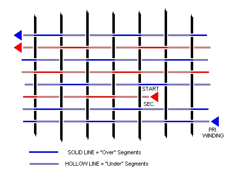
Note on winding L2: The
winding of
L2 is
carefully "synchronized" with the L1 winding so as to preclude any
adjacent
turn segments lying side-by-side. This reduces the L1-L2 coupling
by some small amount. Whether this offers any performance
advantage,
I don't know, but this is good basket-winding practice. For the
'over
2 / under 1' pattern on a 13-point form, synchronized windings can be
had
by following exactly the pattern shown:

The elegance of the Mystery Sets,
the MRL®#
39, and other like sets in the Telefunken genre (untuned secondary
closely
coupled to tuned primary) is what they accomplish with just single-dial
control. The MRL® # 39 is the
epitome:
ONE coil (albeit a special one), ONE capacitor (albeit a special one),
ONE diode -- that's it !
*********************************************************************************************
New!
Further Thoughts
added 18 jun 2004 by Mike Tuggle
Design/Construction
My original intent was to design an
Over-1/Under-1
basket coil with primary and secondary turns lying side-by-side for
maximum
capacitive coupling. But, the needed coil length came out way too
long.
I compromised and wound the Over-2/Under-1 coil described above. This
coil
has a near-perfect 2.5-to-1 diameter-to-length ratio, and its Qs show
it:
unloaded Qs are above 600 over all the band and above 800 over most of
it.
Vernier Readout Scale
I added a vernier readout scale to
the dial
to
help with loggings. Vernier scales are best made by
machine.
Hand-scribing tick marks is exceedingly difficult, and results are
usually
so-so. While the idea is elegant, I'm finding that eyeballing
fractions
of a scale division with a fine hairline pointer is entirely adequate
for
crystal set work.
Initial Results
Performance is quite impressive, although
-- no
surprise
-- it doesn't hold a candle to a double-tuned set. Using a trap
on
a 690 kHz local, I can pick up the 720 kHz 5 kW station on Kauai, 116
miles
away, in the daytime. [I later found it could be pulled in without the
trap.] DX conditions are way down with summer approaching, but in
a few evening sessions I've heard a few of the strongest W.C. stations
including KFI 640 L.A., KPNW 1120 Eugene and KXTA 1150 L.A. The
last
one is by far the most reliable west-coast station here. I'm
looking
forward to improved conditions in the fall.
Antenna Connections
I find the BROAD connection has
sufficient
selectivity
for DXing, plus the advantage of more signal. While the SELECTIVE
antenna connection might be useful for coping in the urban jungle, I
was
thinking of omitting it in future versions of the set, until ...
I went through a systematic test of the 20 possible
antenna-ground
connections with this set. Qualitatively, behavior was similar to
earlier versions: some connections work fine, others not at
all.
One surprise was, at the upper end of the band, the SELECTIVE
connection
was not only more selective, but it was also more sensitive than the
BROAD
connection. The BROAD/SELECTIVE connections might be better
labeled
LOW BAND/HIGH BAND. The crossover is in the 1300 to 1400 kHz
region.
Of course, all this may be specific to the particular antenna-ground
system
being used.
SW QRM Susceptibility
One potential drawback: the set is
susceptible
to lower-end short-wave QRM. Fortunately I only have to contend
with
2.5- and 5 MHz WWVH out here. A small coil in the antenna lead may help
to knock out this QRM.
Telefunken and Other Precedents
It appears that the precedent for
this set
and
the 'Mystery'-type sets is the classic Telefunken circuit that has been
around since the year one:

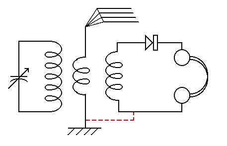
TELEFUNKEN CIRCUIT.
This particular circuit appears in
the
MRL®
literature as the MRL® #4 set. If you
make
the dashed line connection you have the "Mystery Plus" set from the
Brisbane
Sunday Mail, April 16, 1933.
My theory has it that 'Proton'
"invented" the
original Mystery circuit when he screwed up the antenna and ground
attachments
to his Telefunken set. Then, making further "improvements" to his
newfound Mystery set, lo and behold, he arrived back at what is
essentially
the original Telefunken circuit !
Per the MRL®
write-up
(MRL® Handbook-17), it appears it was
correspondent,
Mr. R.B. Richardson, who came up with the two-gang capacitor (so-called
"Tuggle") in the tuning circuit.
Dan Petersen did some interesting,
closely-related
work, starting with the Mystery circuit:
http://www.worldaccessnet.com/~petersen/Mystery-article.htm
Basically, using a two-gang
capacitor in
the Mystery,
Dan 'discovered' the MRL® #39 set ! He
came
up with Broad/Selective configurations different from mine -- possibly
due to our antenna-ground differences.
|